2013年7月18日星期四

Cage control valve leakage treatment

An Overview
    FV-201 anti-surge control valve is concentrated nitric workshop production of a very important field of a regulating valve , if leaking spool valve, process gas in the NO 2 gas directly into the exhaust through the regulating valve, so that the exhaust gas in NO 2 gas concentration excessive emissions, reach environmental requirements. In the November 3, 2010, concentrated nitric sudden increase in the concentration of exhaust workshop, rising from about 100ppm to 600ppm or so, after professional and technical staff to discuss, analyze, judge, agreed that the exhaust gas concentration causes the spool valve FV-201 causing a leak. In order to discharge the requirements of environmental protection, it is necessary to FV-201 control valve for maintenance treatment, the regulating valve leakage reached Ⅴ grade level requirements.
    2 valve structure
    Valve FV-201 manufactured by CCI cage cylinder straight travel valve, the medium flow is low prices, in use, because the original balanced valve plug easily damaged O-ring problem, after the factory will balance structure changed to a non-balanced, and by calculating the existing double-acting cylinder diameter and supply pressure used under unbalanced, still meet the conditions regulating valve under pressure in grade Ⅴ leakage class requirements. Regulating valve seal in the form of single-seat metal seal, linear flow characteristics, nominal diameter DN250, CV value of 900, the cage is designed to reduce the fluid noise porous buck. Double-acting cylinder actuator is equipped with a gas tank, make sure the valve in case of interruption of gas supply can also be emergency opening, to prevent compressor surge occurs.
    3 FV-201 control valve leaks and leakage checks
    3.1 leak check
    Produced in the process with the maintenance stop condition, the FV-201 with inlet and outlet valve regulating valve inlet flange removal separate blind blind flange with DN250 good regulator valve inlet, and add 0.30MPa instrument air source, valve seat, valve parts with soapy water leak, leak observed to determine whether the spool wire seal leaks, or leakage at the valve seat gasket.
    Through the inspection, there is no leakage at the valve seat gasket, leak hole in the cage, and are therefore determined to be in the spool seal leakage.
    3.2 Water pressure leak test
    According GB/T17213.4-2005 "Industrial Control Valves inspection and routine testing in Part IV: Inspection and routine testing" standard leak test, control valve inlet valve cavity to be 0.30MPa irrigation water pressure leak test, collected at the outlet valve leakage of water (see Figure 1), the leakage amounted to 2200ml/min, a large amount of the control valve leakage.
Figure 1 just off valve leaks when pressure test
    According GB/T17213.4-2005 "Industrial Control Valves inspection and routine testing in Part IV: Inspection and routine testing" in 7.3.3 leak specifications, calculate FV-201 control valve hydraulic test Ⅴ grade level requirements leak leak volume. Table 1.
Table 1 FV-201 control valve hydraulic test Ⅴ grade level leakage leakage
    Since FV-201 hydraulic test amount of leakage is 2200ml/min, far greater than Grade Ⅴ valve leakage level required amount of leakage 0.225ml/min, so the need for valve leakage for processing.

FQ647F_16C pneumatic coal injection valve DN32 Design

 Valve models should normally be expressed valve type, drive type, connection type, structural features, sealing surface material, body material and nominal pressures and other factors.Standardization of valve type valve design, selection, sales provides a convenient. Today the type of valve and materials more and more, the valve for the model is more complicated. Although the preparation of a unified standard valve type, but can not meet the growing needs of the development of industrial valves. At present, the valve manufacturer generally uniform numbering method, where the method can not be used uniform numbers, each manufacturer according to their needs develop numbering method. FQ647F-16C pneumatic coal injection valve model based on national standards and the development of methodologies Shantou valve plant shown in Figure 1.
Figure 1 valve type arrangement
     
    Two pairs of valve performance requirements
    FQ647F-16C pneumatic coal injection valve DN32 with reference to international advanced design and manufacture of the prototype of the new structure dedicated coal injection valve, is the metallurgical blast furnace pulverized coal injection system on the device-specific accessories. In order to meet different specifications, different kinds of steel, coal injection valve by turning the blast furnace pulverized coal combustion play a role in raising the temperature of the blast furnace, coal injection system must be ready quickly open and close in order to meet the temperature requirements, and its rapid opening , turn-off is controlled by the computer to achieve. Therefore, pulverized coal pneumatic valve must have the following three characteristics:
    (1) The response speed required to complete in 1 ~ 2s open and close operation to meet the requirements of automatic control computer;
    (2) to stabilize the pressure in the pressure pipe and pipe medium coal incidental leakage of harmful gases, so pneumatic coal injection valve does not leak;
    (3) To protect the sealing surface being pulverized coal injection erosion and wear, do not appear sealing surface strain and stuck (rotation is not flexible) phenomenon, so you must use the fully open or fully closed, prohibited by throttling.
    Three ball design
    3.1 Work
    The ball valve body and the pneumatic device by the two parts. Opening and closing movement by pneumatic actuator - cylinder driven valve stem rotation, so as to drive the ball forward and reverse rotation 90 ° to achieve.
    To open the valve (that is, the sphere diameter flange diameter on the same axis), the compressed air from the actuator of the A-side air intake, push the piston moves backward, the piston rod driven through the turn crank lever rotation, and between the lever and the valve stem cap connected to the use of square, the turn lever is rotated, following the rotation of the stem, but also led to the sphere is rotated clockwise 90 °, so that the valve in the through state, the pressure medium in the pipeline coal through the blast furnace pulverized coal injection valve. When the valve opening, as shown in Figure 2.
Figure 2 valve opening
Figure 3 valve off
    Conversely, to close the valve when the inlet from the B-side, the piston moves forward, driving the ball rotated counterclockwise 90 °, the valve is closed, as shown in Figure 3.
    While the valve is in the fully open or fully closed state, the need to adjust the pneumatic actuator positioning adjustment screws on the two, you can make the ball was fully open or fully closed.
    3.2 Ball Structure Description
    3.2.1 fixed dome structure (shaft-supported)
    To reduce the valve operating torque and enhanced reliability of sealing and avoid compression of the ball is displaced, and the outlet end of the first sealing surface wear, so the ball valve the fixed structure, its structure is shown in Figure 4, which uses The lower shaft of the ball the ball fixed (stem, the sphere and the centerline of the shaft must be on the same axis). Structure in the form of fixed ball valve comes with floating seat, or pressure in the sphere rotates, the valve seat moves, seals are pressed onto the ball, in order to ensure sealing. Usually with the ball of the upper and lower shaft with bronze sleeve bearings or self-lubricating bearings, reduce operating torque.
Figure 4 fixed ball structure
    3.2.2 sealing structure
1 sphere 2 ring 3. Seat 4.O-ring 5 disc spring 6. Adjustable pads 7. Flange
Figure 5 sealing structure
    The sealing structure of the valve shown in Figure 5. Tight seal 2 3 mounted on the seat, the seat 3 in the flange 7 4 sealed by O-rings, seals and 2 by means of disc springs 5 pre-compacted in a sphere, adjust the adjusting shim 6, I can adjust the tight sealing surface than the pressure. To the disc spring seal structure, with a sealing action with automatic compensation. The seal between the gasket and the ball except the pre-compacted by the coned disc spring to ensure sealing, the still rely DWN and seat ring outer diameter D JH loop area formed by the pressing force of the ball on the medium to achieve the seal, seal Reliability depends largely on the average diameter of the sealing surface D MP and the valve seat diameter D JH ratio. If D JH / DMP value is not large enough, the ball will not be able to ensure a reliable seal; if D JH / D MP value is too large, it will cause an overload sealed, leaving the valve switching torque increases, accelerated wear and tear.
http://higeroindustry.com/

2013年7月11日星期四

What Is A Control Valve?

From  http://www.higeroindustry.com/

Control Valve with PositionerProcess plants consist of hundreds, or even thousands, of control loops all networked together to produce a product to be offered for sale. Each of these control loops is designed to keep some important process variable such as pressure, flow, level, temperature, etc. within a required operating range to ensure the quality of the end product. Each of these loops receives and internally creates disturbances that detrimentally affect the process variable, and interaction from other loops in the network provides disturbances that influence the process variable.

To reduce the effect of these load disturbances, sensors and transmitters collect information about the process variable and its relationship to some desired set point. A controller then processes this information and decides what must be done to get the process variable back to where it should be after a load disturbance occurs. When all the measuring, comparing, and calculating are done, some type of final control element must implement the strategy selected by the controller. The most common final control element in the process control industries is the control valve. The control valve manipulates a flowing fluid, such as gas, steam, water, or chemical compounds, to compensate for the load disturbance and keep the regulated process variable as close as possible to the desired set point.
Many people who talk about control valves or valves are really referring to a control valve assembly. The control valve assembly typically consists of the valve body, the internal trim parts, an actuator to provide the motive power to operate the valve, and a variety of additional valve accessories, which can include positioners, transducers, supply pressure regulators, manual operators, snubbers, or limit switches. Whether it is called a valve, control valve or a control valve assembly is not as important as recognizing that the control valve is a critical part of the control loop. It is not accurate to say that the control valve is the most important part of the loop. It is useful to think of a control loop as an instrumentation chain. Like any other chain, the whole chain is only as good as its weakest link. It is important to ensure that the control valve is not the weakest link. Following are definitions for process control, sliding-stem control valve, rotary-shaft control

Sliding-Stem Control Valve Terminology (Part 1)

Control Valve Direct Acting Actuator
Control Valve air to open
Control Valve body
Actuator Spring: A spring, or group of springs, enclosed in the yoke or actuator casing that moves the actuator stem in a direction opposite to that created by diaphragm pressure.
Actuator Stem: The part that connects the actuator to the valve stem and transmits motion (force) from the actuator to the valve.
Actuator Stem Extension: An extension of the piston actuator stem to provide a means of transmitting piston motion to the valve positioner
Actuator Stem Force: The net force from an actuator that is available for actual positioning of the valve plug.
Angle ValveA valve design in which one port is co-linear with the valve stem or actuator, and the other port is at a right angle to the valve stem.
Control Valve bellow seal

Bellows Seal Bonnet: A bonnet that uses a bellows for sealing against leakage around the closure member stem
Bonnet: The portion of the valve that contains the packing box and stem seal and can guide the stem. It provides the principal opening to the body cavity for assembly of internal parts or it can be an integral part of the valve body. It can also provide for the attachment of the actuator to the valve body. Typical bonnets are bolted, threaded, welded, pressure-seals, or integral with the body. (This term is often used in referring to the bonnet and its included packing parts. More properly, this group of component parts should be called the bonnet assembly.)
Bonnet Assembly: (Commonly Bonnet, more properly Bonnet Assembly): An assembly including the part through which a valve stem moves and a means for sealing against leakage along the stem. It usually provides a means for mounting the actuator and loading the packing assembly.
Bottom Flange: A part that closes a valve body opening opposite the bonnet opening. It can include a guide bushing and/or serve to allow reversal of the valve action.
Bushing: A device that supports and/ or guides moving parts such as valve stems.
Control Valve trim
Cage: A part of a valve trim that surrounds the closure member and can provide flow characterization and/or a seating surface. It also provides stability, guiding, balance, and alignment, and facilitates assembly of other parts of the valve trim. The walls of the cage contain openings that usually determine the flow characteristic of the control valve.
Closure Member: The movable part of the valve that is positioned in the flow path to modify the rate of flow through the valve.
Closure Member Guide: That portion of a closure member that aligns its movement in either a cage, seat ring, bonnet, bottom flange, or any two of these.
Cylinder: The chamber of a piston actuator in which the piston moves
Cylinder Closure Seal: The sealing element at the connection of the piston actuator cylinder to the yoke.
Diaphragm: A flexible, pressure responsive element that transmits force to the diaphragm plate and actuator stem.
Diaphragm Actuator: A fluid powered device in which the fluid acts upon a flexible component, the diaphragm.
Diaphragm Case: A housing, consisting of top and bottom section, used for supporting a diaphragm and establishing one or two pressure chambers.
Diaphragm Plate: A plate concentric with the diaphragm for transmitting force to the actuator stem.
Direct Actuator: A diaphragm actuator in which the actuator stem extends with increasing diaphragm pressure.
Extension Bonnet: A bonnet with greater dimension between the packing box and bonnet flange for hot or cold service.


Sliding-Stem Control Valve Terminology (Part 2)

Control Valve
Globe Valve: A valve with a linear motion closure member, one or more ports, and a body distinguished by a globular shaped cavity around the port region. Globe valves can be further classified as: two-way single-ported; two-way double-ported; angle-style ; three-way ; unbalanced cage-guided ; and balance cage-guided.
Lower Valve Body: A half housing for internal valve parts having one flow connection. The seat ring is normally clamped between the upper valve body and the lower valve body in split valve constructions.
Offset Valve: A valve construction having inlet and outlet line connections on different planes but 180 degrees opposite each other.
Packing Box (Assembly): The part of the bonnet assembly used to seal against leakage around the closure member stem. Included in the complete packing box assembly are various combinations of some or all of the following component parts: packing, packing follower, packing nut, lantern ring, packing spring, packing flange, packing flange studs or bolts, packing flange nuts, packing ring, packing wiper ring, felt wiper ring, belleville springs, anti-extrusion ring.
Piston: A movable pressure responsive element that transmits force to the piston actuator stem
Piston Type Actuator: A fluid powered device in which the fluid acts upon a movable piston to provide motion to the actuator stem. Piston type actuators are classified as either double-acting, so that full power can be developed in either direction, or as spring-fail so that upon loss of supply power, the actuator moves the valve in the required direction of travel.
Plug: A term frequently used to refer to the closure member.
Port: The flow control orifice of a control valve.
Retaining Ring: A split ring that is used to retain a separable flange on a valve body.
Control Valve Reverse Acting Actuator
Reverse Actuator: A diaphragm actuator in which the actuator stem retracts with increasing diaphragm pressure. Reverse actuators have a seal bushing installed in the upper end of the yoke to prevent leakage of the diaphragm pressure along the actuator stem.
Rubber Boot: A protective device to prevent entrance of damaging foreign material into the piston actuator seal bushing.
Seal Bushing: Top and bottom bushings that provide a means of sealing the piston actuator cylinder against leakage. Synthetic rubber O-rings are used in the bushings to seal the cylinder, the actuator stem, and the actuator stem extension.
Seat: The area of contact between the closure member and its mating surface that establishes valve shut-off.
Seat Load: The net contact force between the closure member and seat with stated static conditions. In practice, the selection of an actuator for a given control valve will be based on how much force is required to overcome static, stem, and dynamic unbalance with an allowance made for seat load.
Seat Ring: A part of the valve body assembly that provides a seating surface for the closure member and can provide part of the flow control orifice.
Separable Flange: A flange that fits over a valve body flow connection. It is generally held in place by means of a retaining ring.
Spring Adjustor: A fitting, usually threaded on the actuator stem or into the yoke, to adjust the spring compression.
Spring Seat: A plate to hold the spring in position and to provide a flat surface for the spring adjustor to contact.
Static Unbalance: The net force produced on the valve stem by the fluid pressure acting on the closure member and stem with the fluid at rest and with stated pressure conditions.
Stem Connector: The device that connects the actuator stem to the valve stem.
Trim: The internal components of a valve that modulate the flow of the controlled fluid. In a globe valve body, trim would typically include closure member, seat ring, cage, stem, and stem pin.
Trim, Soft-Seated: Valve trim with an elastomeric, plastic or other readily deformable material used either in the closure component or seat ring to provide tight shutoff with minimal actuator forces.
Upper Valve Body: A half housing for internal valve parts and having one flow connection. It usually includes a means for sealing against leakage along the stem and provides a means for mounting the actuator on the split valve body.
Valve Body: The main pressure boundary of the valve that also provides the pipe connecting ends, the fluid flow passageway, and supports the seating surfaces and the valve closure member. Among the most common valve body constructions are:
a) single-ported valve bodies having one port and one valve plug;
b) double-ported valve bodies having two ports and one valve plug;
c) two-way valve bodies having two flow connections, one inlet and one outlet;
d) three-way valve bodies having three flow connections, two of which can be inlets with one outlet (for converging or mixing flows),
or one inlet and two outlets (for diverging or diverting flows). The term valve body, or even just body, frequently is used in referring to the valve body together with its bonnet assembly and included trim parts. More properly, this group of components should be called thevalve body assembly.
Valve Body Assembly (Commonly Valve Body or Valve, more properly Valve Body Assembly)An assembly of a valve, bonnet assembly, bottom flange (if used), and trim elements. The trim includes the closure member, which opens, closes, or partially obstructs one or more ports.
Valve Plug: A term frequently interchanged with plug in reference to the closure member.
Valve Stem: In a linear motion valve, the part that connects the actuator stem with the closure member.
Yoke: The structure that rigidly connects the actuator power unit to the valve.

Solenoid valve

  Solenoid valve is used to control the automation of basic components of fluid, is actuator; not limited to hydraulic, pneumatic. Solenoid valve used to control the direction of hydraulic flow machines in plant generally controlled by hydraulic cylinder, the solenoid valve will be used. 
    The working principle of electromagnetic valve, solenoid valve in a closed chamber, in a different position with holes, each hole leads to a different pipeline, valve chamber in the middle, both sides are two electromagnets, which side of the magnet coil power valve will be attracted to which side, by controlling the body's movement to a different file live or leaked oil discharge hole, and into the hole is always open, hydraulic oil flows to different hoses, and then oil pressure to push oil just the piston, piston rod then drive the piston rod drive mechanism moving. This current by controlling the electromagnet to control the mechanical movement. 
http://www.higeroindustry.com/

RF Waveguide Vacuum Valve

Description

The device enables low-loss Radio Frequency power transmission in a waveguide across a gap, where a liftable instrument is positioned. Originally designed with a wall as the instrument making the device function as a valve, to solve the problem of maintaining vacuum on one side and atmospheric pressure on the other side. When the system is in operation and the valve is open, the technology provides low-loss high power RF transmission.
In order to maintain one part of a RF system evacuated while doing installation and maintenance on the other part, dielectric windows are normally used. High power RF makes the dielectric break down and windows can therefore not be used. The RF waveguide vacuum valve was developed for CERN’s CLIC project to maintain vacuum and to reduce maintenance costs.

Area of expertise

Mechanics

Applications

  • Waveguide systems - Medical and Industrial field and Scientific accelerator.
  • Satellite & Space Research - The technology may be used to evacuate RF satellite systems using vacuum, in space.

Innovative features

No surface electric field in the waveguide section because of TE0n mode conversion, which increases the potential of high power RF transmission because of low loss.

Specifications

A 30 GHz dual-mode vacuum valve with an overall length of 100 mm and a diameter of the central waveguide section, that contains the TE01+TE02 mode mixture, of 30 mm the transmission measurements show losses of about -0.1dB. These losses consist of two contributions: diffraction losses of -0.033dB and ohmic losses of -0.049dB.

Advantages

  • The possibility to use a commercially available vacuum valve in waveguides where high-power – high-frequency is used.
  • Low loss.
  • There are no limitations on the frequency range of the technology. This technology can be used from the lowest frequencies under which vacuum waveguides are used up to quasi-optical transmission lines.
  • The technology can be a clean environmental friendly alternative to the use of SF6, a highly potent green house gas.

Intellectual Property status

The technology has been proven by simulations of different frequencies (from 3 to 30 GHz) and a prototype for 30 GHz has been built. An international patent application is filed and the technology is ready for licensing.

2013年7月9日星期二

Triple Offset, Metal-Seated Butterfly Valves - Principle Of Operation

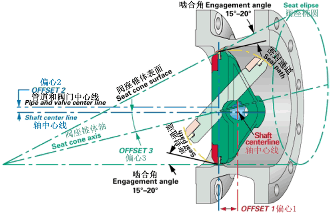
The NVF Triple Offset butterfly valve provides a bi-directional bubble tight shut-off. This geometry ensures that the disc seal contacts the body seat only at the final shut-off position without rubbing or galling, providing a torque generated resilient seal with sufficient “wedging” to ensure a uniform seal contact.
THE TRIPLE OFFSET GEOMETRY
 
OFFSET 1The shaft is offset behind the seat axis to allow complete sealing contact around the entire seat
 
OFFSET 2The shaft centerline is offset from the pipe and valve which provides interference free opening and closing of the valve
 
OFFSET 3The seat cone axis is offset from the shaft centerline to eliminate friction during closing and opening and to achieve uniform compressive sealing around the entire seat.

 Friction Free Sealing For Long Cycle Life


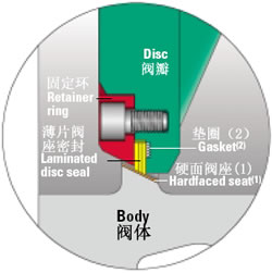
NVF provides an extra rigid retaining ring with bolting, resulting from ASME stress calculations.
(1) Seat is hardfaced with Stellite as standard.
(2) The gasket is spiral wound SS/Graphite for zero leakage
 

THE LAMINATED DISC SEAL
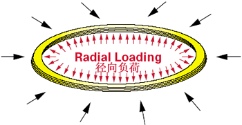
Seating forces are generated by the torque during closing uniformly around the entire circumference. The resilient seal flexes and energizes, assuming the shape of the seat. The compression forces equally distributed around the perimeter provide a tight bi-directional shut off. The resiliency of the seal allows the valve body and disc to contract or expand, without the risk of jamming due to temperature fluctuations. It is self-adjusting.
From:  valve knowledge

Valves & Actuators 101 Course Set for Valve World Americas Event

The second Valve World Americas 2013 Expo & Conference begins at Houston’s George R. Brown Convention Center on June 25, 2013, but the great opportunities for learning start even before the conference.
Greg-BR-presentingGreg JohnsonThe Valve Manufacturers Association (VMA) is offering a one-day version of its Valves & Actuators 101 education program, designed to jump-start the career of industry newcomers or provide a refresher on valve, actuator and control basics. VMA member presenters will discuss the major valve and actuator types from 9 am to 5 pm on Monday, June 24.
The 2013 Valve World Americas Expo & Conference is the perfect complement to the valves and actuators course as it will provide an American-focused platform for the ongoing technical and commercial exchange of information and experiences on the latest technologies, developments and products for the valve industry.
The conference will feature workshops on topics including material selection, fugitive emissions, fitness for service, updates in cryo technology, unconventional energy and more. Each day has keynote sessions on topics such as the general outlook on energy and new challenges in the field.
Additionally, 147 exhibitors from 15 countries will be displaying at the expo, presenting a complete spectrum of innovations for this sector, ranging from valves, valve-related products and valve-related piping products to seals and sealing materials, engineering and leak detection, and valve repair services. In addition to exhibits hosted by a number of VMA members, Valve Manufacturers Association staff will be on hand to answer questions about the association, and distribute copies of VALVE Magazine and the latest Valve Catalog.
Visit the Valve World Americas website and register for the 101 course by June 19. The cost is $450 and attendees receive a VMA Certificate of Completion for six continuing education hours, CD with presentations, lunch and afternoon snack, plus complimentary entrance to the Valve World Americas Expo.

Two-day 101 Course to Take Place in November

P1010444Later this year, VMA will conduct its full two-day Valves & Actuators 101 course, Nov. 6-7, 2013, at Harrah’s in New Orleans. The Valve Basics Seminar & Exhibits has been expanded and, in addition to the regular program, now includes lessons on Solenoids & Limit Switches, and Positioners & Accessories. The popular "Valve Petting Zoo” and a table-top exhibition also will take place.
More than 750 people have attended VMA’s Valves & Actuators 101 course since it was introduced in late 2009. VMA will soon release an online, narrated version of the course to provide even more access to this vital, entry-level education.
For more information and online registration, visit VMA.org > Meetings > Basics Seminar & Exhibits. The cost is $665 through Aug. 31, and then rises to $700. The fee includes a VMA Certificate of Completion awarding 12 continuing education hours, a manual with presentations and notes, breakfasts, lunches, snacks and a reception. For more information, contact Judy Tibbs, VMA director of education.

2013年7月2日星期二

JIS Butterfly valve - higero valves


JIS Butterfly valve


Detailed


Product Name
Japanese standard butterfly valve
Product Type
D373H
Suitable medium :
Water, steam, oil, water, etc.
Caliber
DN40-600
Product pressure
0.6~6.4Mpa
Material
Steel, stainless steel, etc.
Suitable temperature-29~550℃


日标硬密封用途及特点: 

D373H-10K、20K、和D343H-10K、20K系列的主要结构特征为对夹式和法兰式三偏心密封形式,阀座密封圈采用弹性密封和软硬兼容的多层次密封两种结构,其密封性能可靠。确保开启时蝶板不接触密封座,消除了密封座不均匀负载,延长了使用寿命,确保可靠的密封性能,具有耐高温、耐磨损、耐腐蚀等优点。广泛应用于石油、化工及工业环保水处理、高层建筑、给排水等管道上。

日标硬密封采用标准:

设计标准: APl609-1983
法兰连接尺寸: JIS B2212;JlS B2213;JIS B2214
结构长度: JlS B2002-1987;
压力试验: JlS B2003-1987;

日标硬密封主要技术参数:


公称通径
DNmm
2″~48″
2″~48″
公称压力
PNMPa
10K
20K
试验压力 PsMPa
强度试验
1.5
3.0
密封试验
1.1
2.2
适用介质
水、蒸汽、油品、海水等
适用温度
-29~550℃
日标硬密封主要零件的材质:
零件名称
材料
阀体
WCB、304、316、316SS、CF8M
阀板
WCB、304、316、316SS、CF8M
阀杆
304、316、2Crl3、1Crl8Ni9Ti
密封圈
304、316、氟塑料
填料
柔性石墨、氟塑料
传动方式
手柄、蜗轮、气动、电动等

D37/3/5H-10K20K系列日标硬密封
公称通径
结构长度
标准值
外形尺寸参考值
连接尺寸标准值
H
D373H
D673H
D973H
10K
20K
mm
inch
L
H1
A1
B1
H2
A2
B2
H3
A3
B3
D1
Z-d
D1
Z-d
50
2
43
112
350
180
200
625
245
72
530
250
255
120
4-19
120
8-19
65
21/2
46
115
370
180
200
625
245
72
530
250
255
140
4-19
140
8-19
80
3
49
120
380
180
200
645
245
72
565
250
255
150
8-19
160
8-23
100
4
56
138
420
180
200
675
355
92
600
250
255
175
8-19
185
8-23
125
5
64
164
460
180
200
715
355
92
640
250
255
210
8-23
225
8-25
150
6
70
175
555
270
280
800
355
92
705
300
315
240
8-23
260
12-25
200
8
71
208
605
270
280
850
250
170
775
300
315
290
12-23
305
12-25
250
10
76
243
680
270
280
925
250
170
945
300
315
355
12-25
380
12-27
300
12
83
283
800
380
420
1035
450
220
1070
300
315
400
16-25
430
16-27
350
14
92
310
835
380
420
1070
450
220
1140
300
315
445
16-25
480
16-33
400
16
102
340
915
450
470
1190
450
220
1210
300
315
510
16-27
540
16-33
450
18
114
380
960
480
490
1250
650
280
1335
575
714
565
20-27
605
20-33
500
20
127
410
1020
480
490
1290
650
280
1415
575
714
620
20-27
660
20-33
600
24
154
470
1225
480
490
1455
850
380
1605
656
810
730
24-33
770
24-39
700
28
165
550
1355
640
660
1585
850
380
1844
656
810
840
24-33
900
24-48
800
32
190
640
1470
640
660
1700
1250
380
2040
656
810
950
28-33
1030
24-56
900
36
203
710
1545
750
860
1965
1250
380
2255
785
863
1050
28-33
1140
28-56
1000
40
216
770
1 795
850
900
2015
1250
380
2380
785
863
1160
28-39


1200
48
254
890
1965
850
900
2250
1250
380
2640
785
863
1380
32-39


D34/3/5H-10-K20K系列日标硬密封
公称通径
结构长度
标准值
外形尺寸参考值
连接尺寸标准值
L
H
D343H
D643H
D943H
10K
20K
mm
inch
H1
A1
B1
H2
A2
B2
H3
A3
B3
D
D1
Z-d
D
D1
Z-d
50
2
108
150
112
350
180
200
605
245
72
530
250
255
155
120
4-19
155
120
8-19
65
21/2
112
170
115
370
180
200
625
245
72
530
250
255
175
140
4-19
175
140
8-19
80
3
114
180
120
380
180
200
645
245
72
565
250
255
185
150
8-19
200
160
8-23
100
4
127
190
138
420
180
200
675
355
92
600
250
255
210
175
8-19
225
185
8-23
125
5
140
200
164
460
180
200
715
355
92
640
250
255
250
210
8-23
270
225
8-25
150
6
140
210
175
555
270
280
800
355
92
705
300
315
280
240
8-23
305
260
12-25
200
8
152
230
208
605
270
280
850
250
170
775
300
315
330
290
12-23
350
305
12-25
250
10
165
250
243
680
270
280
925
250
170
945
300
315
400
355
12-25
430
380
12-27
300
12
178
270
283
800
380
420
1035
450
220
1070
300
315
445
400
16-25
480
430
16-27
350
14
190
290
310
835
380
420
1070
450
220
1140
300
315
490
445
16-25
540
480
16-33
400
16
216
310
340
915
450
470
1190
450
220
1210
300
315
560
510
16-27
605
540
16-33
450
18
222
330
380
960
480
490
1250
650
280
1335
575
714
620
565
20-27
675
605
20-33
500
20
229
350
410
1020
480
490
1290
650
280
1415
575
714
675
620
20-27
730
660
20-33
600
24
267
390
470
1225
480
490
1455
850
380
1605
656
810
795
730
24-33
845
770
24-39
700
28
292
430
550
1355
640
660
1585
850
380
1844
656
810
905
840
24-33
995
900
24-48
800
32
318
470
640
1470
640
660
1700
1250
380
2040
656
810
1020
950
28-33
1140
1030
24-56
900
36
330
510
710
1545
850
900
1865
1250
380
2255
785
863
1120
1050
28-33
1250
1140
28-56
1000
40
410
550
770
1795
850
900
2015
1500
580
2380
785
863
1235
1160
28-39


1200
48
470
630
890
1965
850
900
2226
1500
580
2640
785
863
1465
1380
32-39